As you most likely know, Minecraft is a voxel (block-based) game published in 2011 though still regularly updated to this day, loved for its simple premise of surviving and building. However, there is another side to Minecraft, involving the game mechanic called redstone. Redstone is a way of creating ‘circuits’ which can react to input and produce output in a number of different ways, often used to create resource farms and contraptions like doors.
I’ve always been fascinated by redstone, wondering what the limits are for building complex devices involving complicated logic. Of course, this was a long time ago before I had any computer science knowledge. Now I see redstone as a sort of state machine (since it doesn’t require a power source), with the ability to store and process data. These are the requirements of a system to be Turing complete, which means: you can build a computer using redstone!
I’m definitely not the first person to have this thought, since there are countless other redstone computers documented on YouTube, and even tutorials to get you started on the official Minecraft wiki. However, I still wanted to try to create a computer myself, and eventually I did.
Architecture
During my first year of University, one of my modules used a set of tools borrowed from the nand2tetris course created by Noam Nisan and Shimon Schocken. This course teaches you about the structure of a CPU by having you construct a computer from scratch using a basic Hardware Description Language. The computer you build is known as the Hack Computer, which was designed for this course. Due to the simplicity of this architecure, I decided to use it as the foundation for my Minecraft computer. The architecure is 16-bit for both addresses and data, and uses the Harvard architecture model where instructions are stored seperately from data in read-only memory.
Instructions
There are two instructions, A instructions and C instructions, although the latter is more like multiple instructions in one. A instructions have 0 in their most significant bit and load the other 15 bits into the ‘A’ register. C instructions have 1 in their most significant bit and denote a computation, including where the output should be stored and if the program should branch (jump to a different instruction).
Registers
Other than the program counter, there are two physical registers in the Hack CPU, as well as one ‘virtual’ register.
The D Register
The data register is a general-purpose register that’s usually used to store working values during calculations, or as a temporary space to hold a value from memory when you want to use another memory value in a calculation. It is connected directly to the output of the ALU.
The A Register
The address register is used to control which address of RAM is being accessed, and can also control ROM via a jump instruction. However, it can also be used as a general-purpose register since it’s value can be used as an input to the ALU. It is connected to both the output of the ALU and the instruction input bus.
The M Register
The memory register is treated no differently the D or A registers, but actually refers to the currently accessed location in RAM, which makes it extremely useful for storing multiple values at a time.
You can read more about the Hack computer architecture here.
Designing the CPU
Before I could build any kind of data processing logic, I needed to build up some fundamental components. While I could have built everything using NAND gates as the base, in the same way nand2tetris does, this would have made the build too large and slow, so I instead decided to build each component with the most efficient design I could come up with.
Multiplexer
The first component I designed was the multiplexer (or mux for short). This switches its output between two inputs, with a single bit input for controlling it. My design for the mux used the ‘comparator’ redstone component in subtract mode, to either allow or disallow a signal to get past a point. Each input is connected to one of these, but with opposite settings, so only one them reaches an OR gate for the output
Not selector
The design of the ALU requires the ability to select between a value and it’s inverse. Since it is used multiple times I created a component for it, which is based on the mux where the second input is the NOT of the first input.
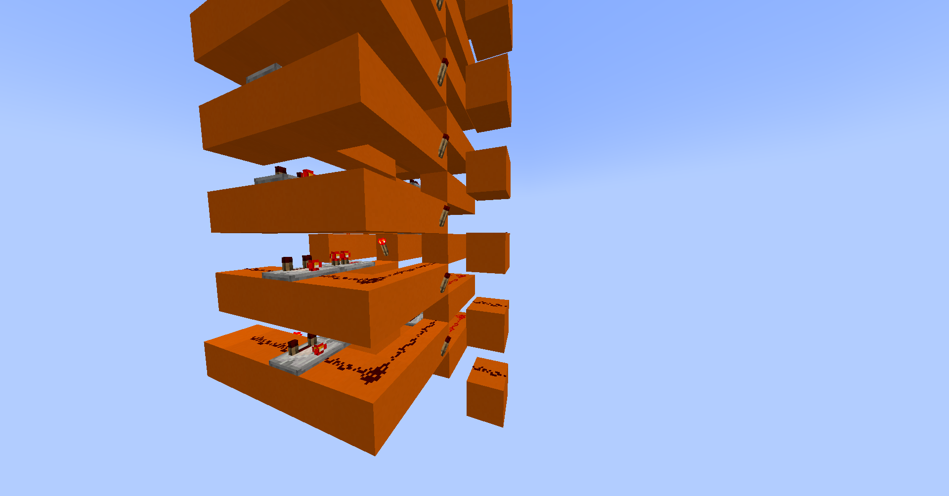
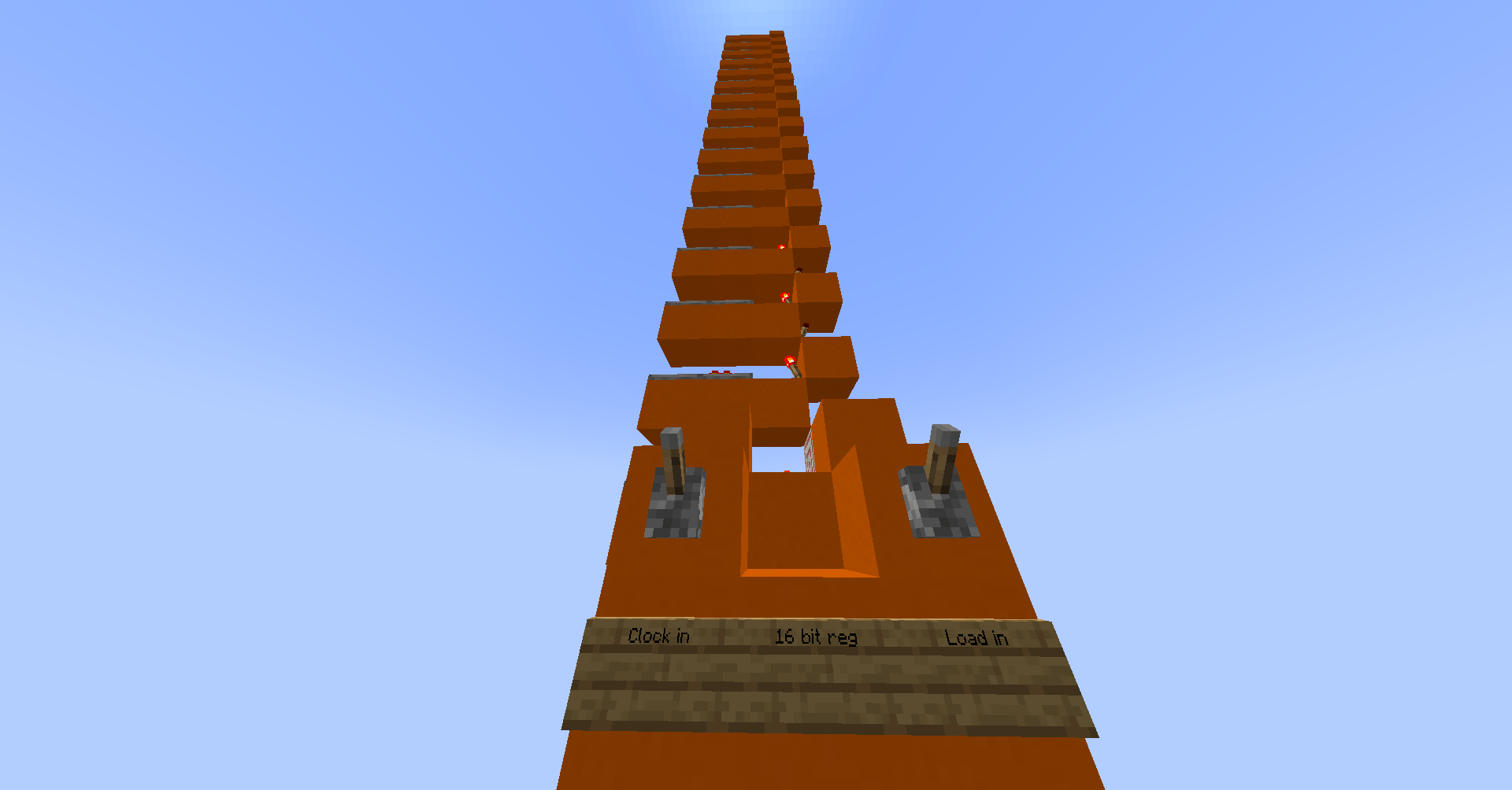
Register
Registers are used to store working values inside the CPU. They always output the value stored in them, and they only store the value from their input when a ‘load’ flag is set (and only change on the clock signal).
My register uses the ‘repeater locking’ mechanic which allows the state of a repeater to be saved when another repeater provides a signal from the side. To store a value you simply to ‘unlock’ the repeater and then lock it again once the value is in place.

Adder
Adding two numbers together is not actually that difficult, however the logic required for it can take up a lot of space. To add two 16-bit numbers, you need 16 full adders (it’s actually 15 full adders and 1 half adder, but we’ll call it 16 for simplicity). A full adder takes three inputs: A, B and the carry bit from the previous adder. The circuit requires two XOR gates, and AND gate and an OR gate. I designed my full-adder to be vertically stackable:


This stackable design meant I could simply copy and paste (15 times) to create my 16-bit adder:
AND Gate
The AND gate is fairly simple with redstone, so I was able to design one without much trouble. I used de Morgan’s law to change the logic equation to NOT ((NOT A) OR (NOT B)), then used redstone torches to implement it.
Add One
One useful circuit is an adder which only adds 1 to the given input. While I could’ve used a full adder, much of the logic would be unused since the second input is constant (1). Instead I used a series of half adders which took input from the carry output of the half-adder below, which has the effect of adding one to the original value. This simplified design allows the program counter, which uses this part, to be much smaller.
The ALU
The arithmetic logic unit, or ALU for short, is the part of the CPU that does calculations. The hack ALU takes two 16-bit inputs, x and y, and 6 control flags: ‘zero x’, ‘not x’, ‘zero y’, ‘not y’, function (AND or add) and ‘not output’. Alongside the main 16-bit output, there are two output flags for ‘output is negative’ and ‘output is zero’.
Constructing the ALU was mostly glueing together the pieces that I already designed. I spent a while manually inputing values to validate that it worked correctly, and flattened a few bugs I found in the process.
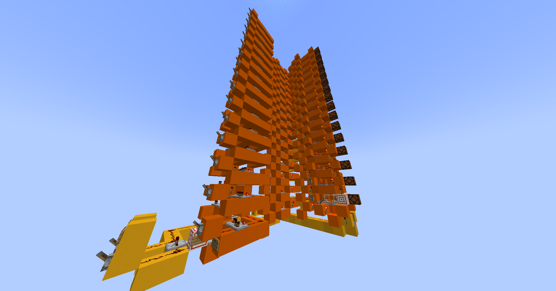
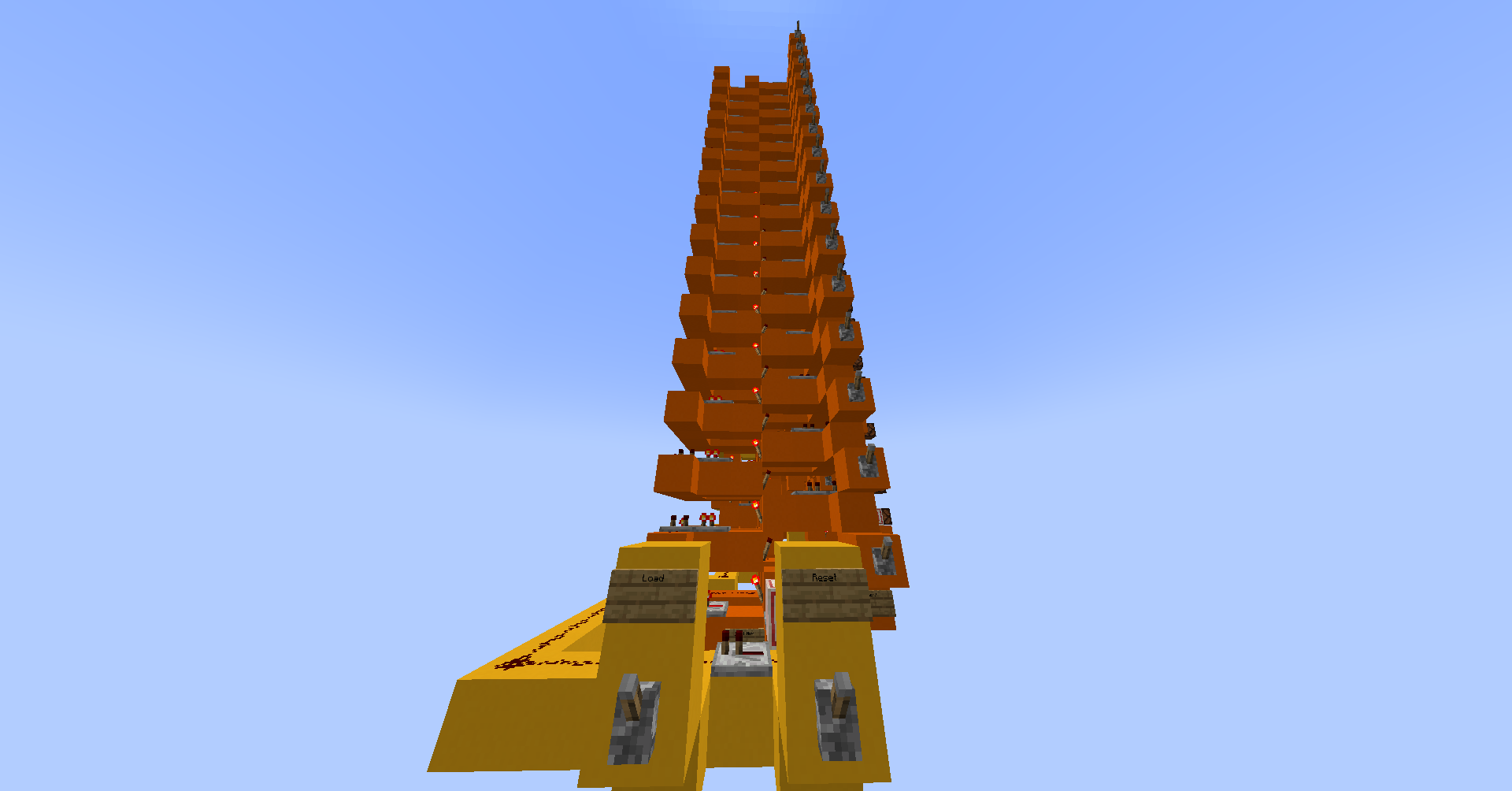
Program Counter
The program counter is a special-purpose register which cannot be directly accessed, but is instead controlled through branching. It outputs the address of the next instruction to executed, which is then sent to ROM to be loaded. Each clock cycle, its value should increment to point to the next instruction. If the previous instruction involved jumping to a different part of ROM, then a new value is loaded into the PC instead. There is also the reset flag which causes the PC to reset to zero on the next clock cycle.
Finishing off the CPU
To complete the CPU, I added the A and D registers, the program counter, and the control lines for decoding instructions. I then tested it by manually playing the part of instruction memory, placing values on the instruction bus before cycling the clock, then checking that the registers contained the expected values.

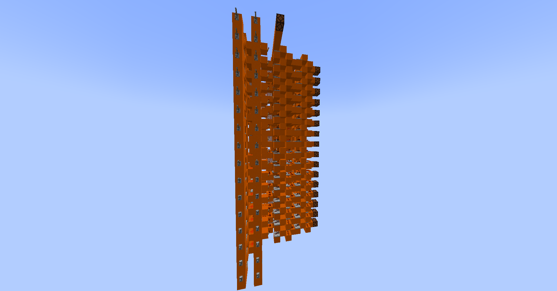
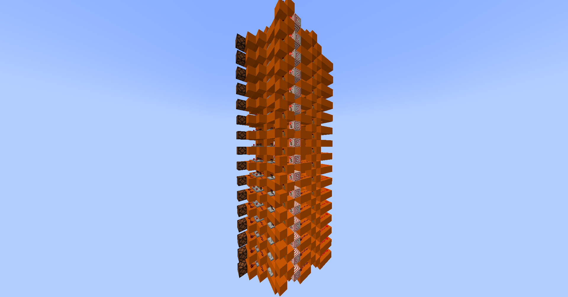
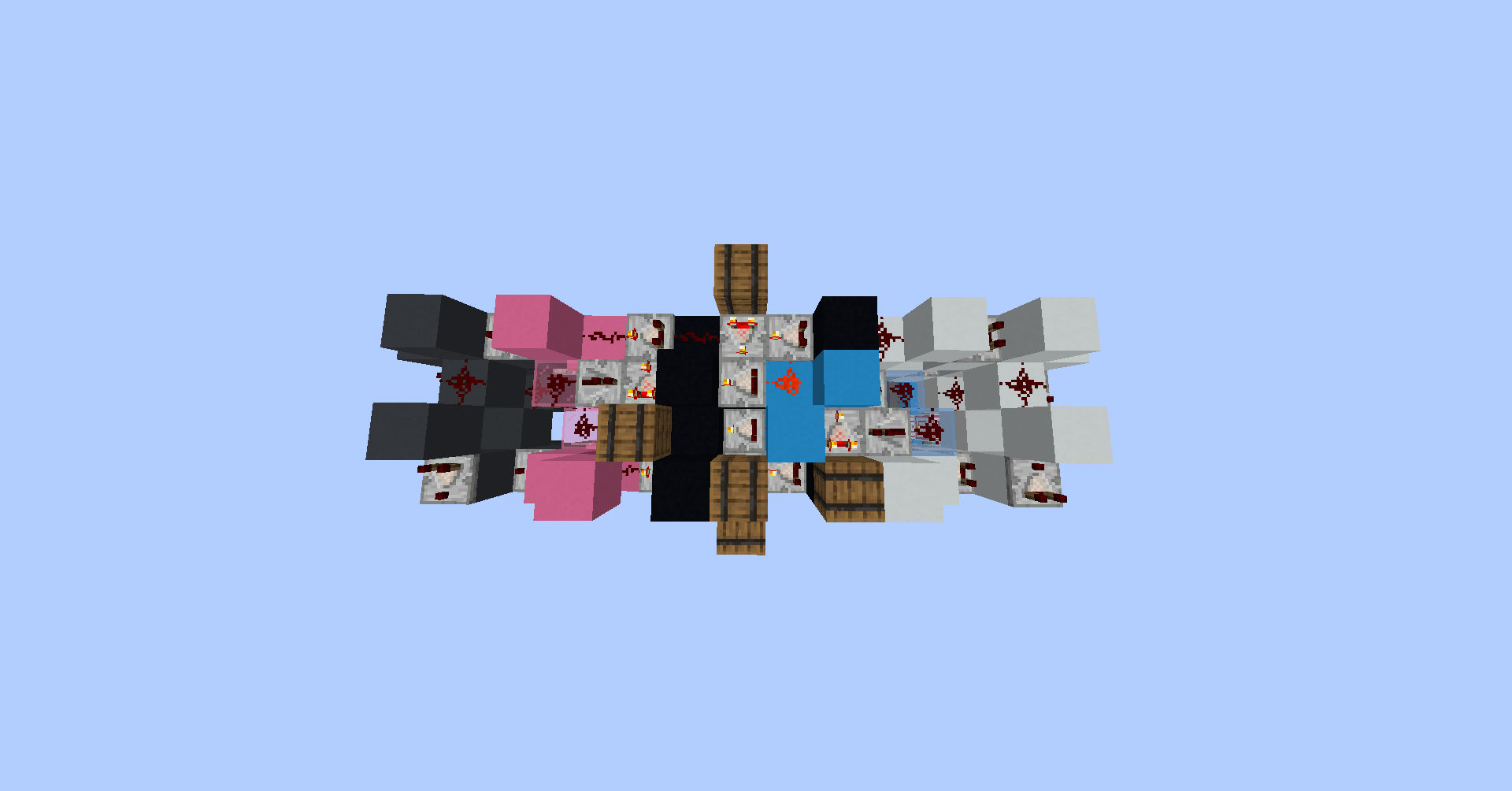
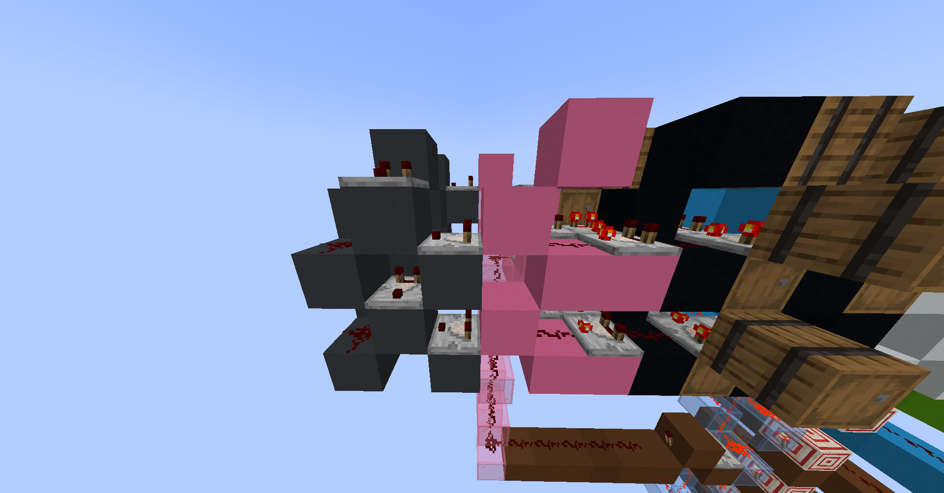
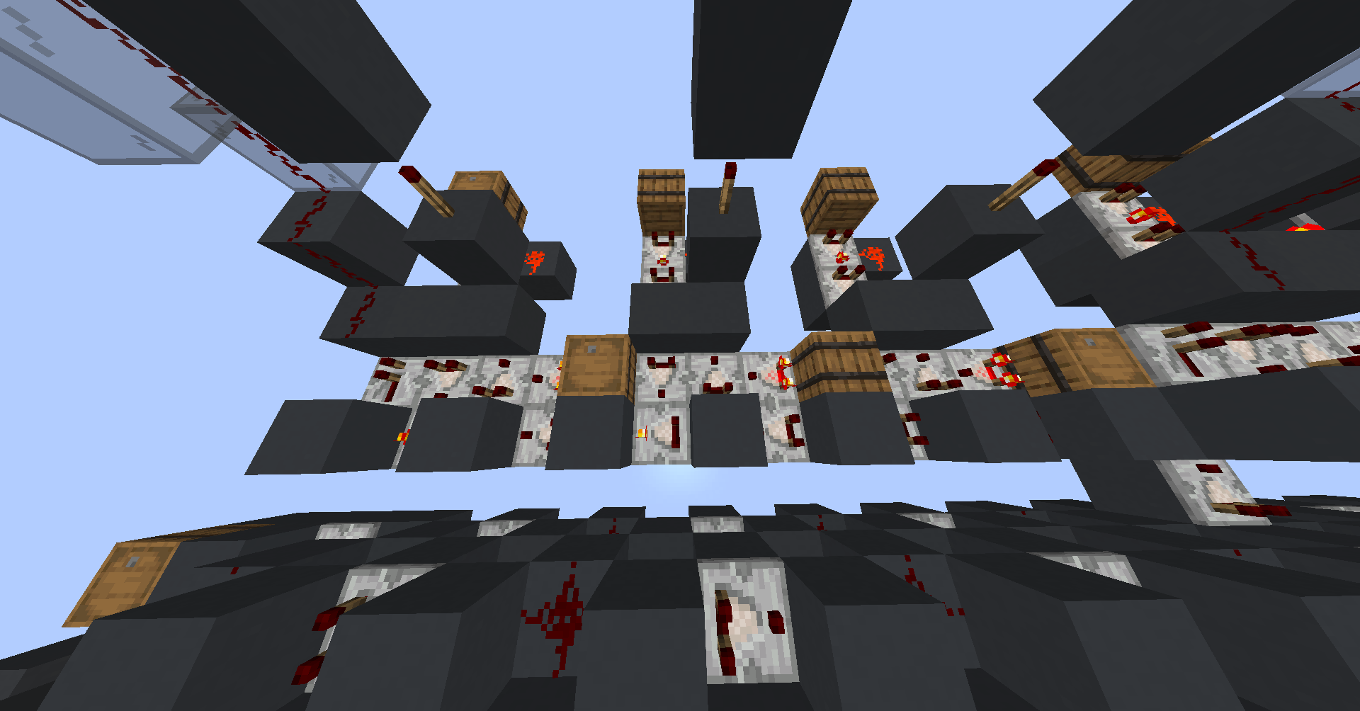
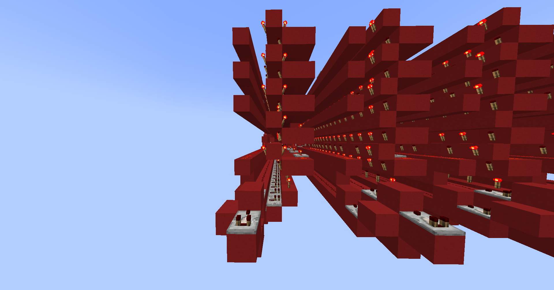
ROM
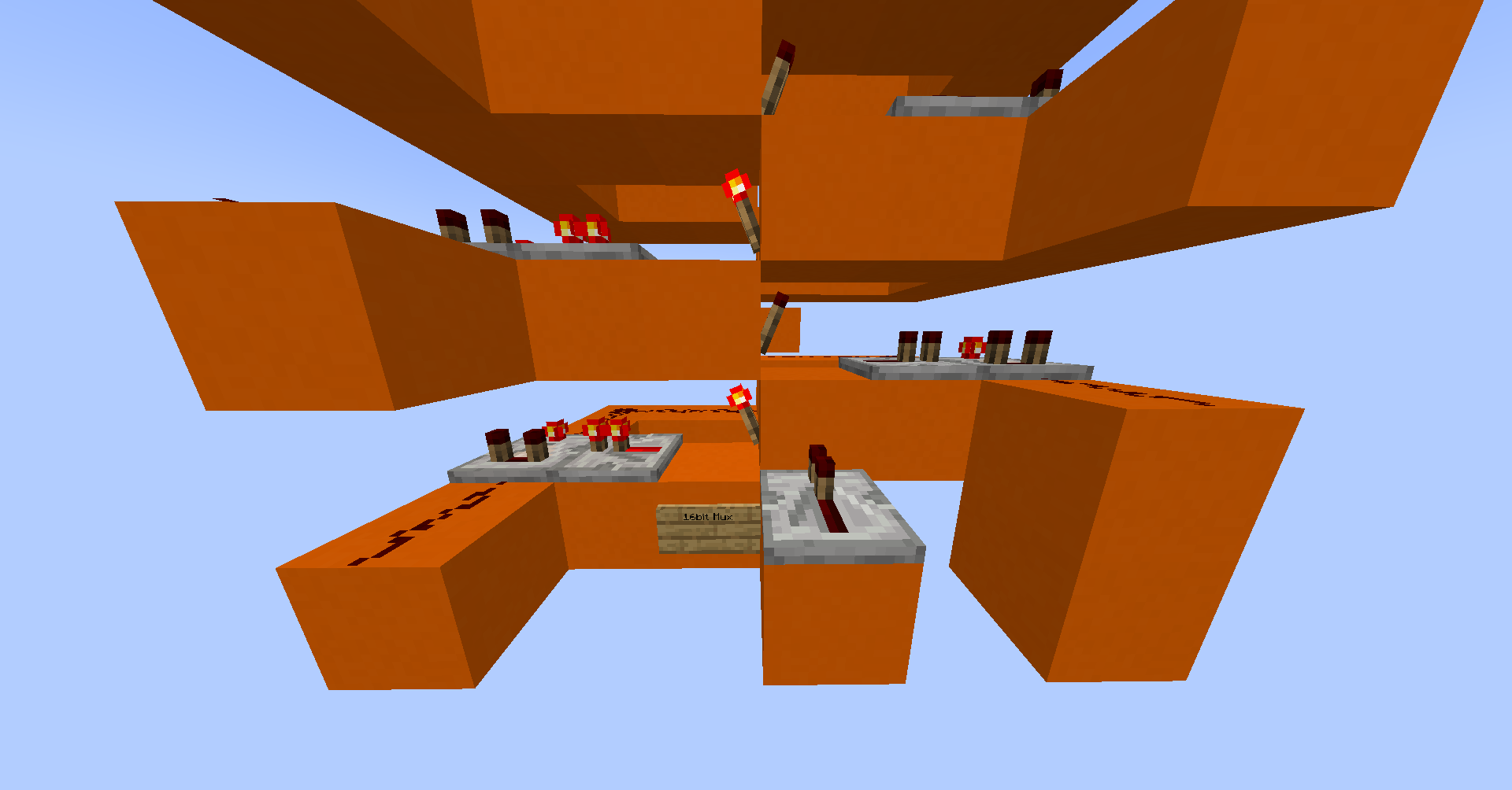
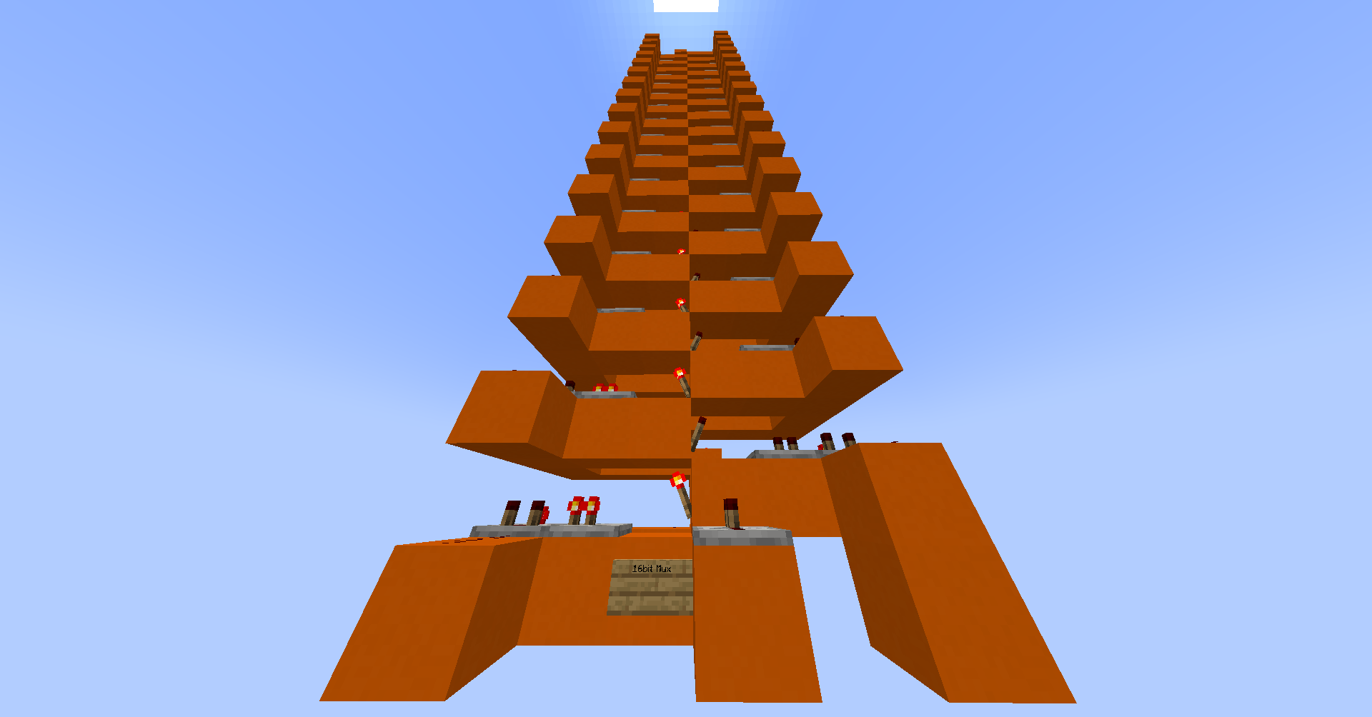
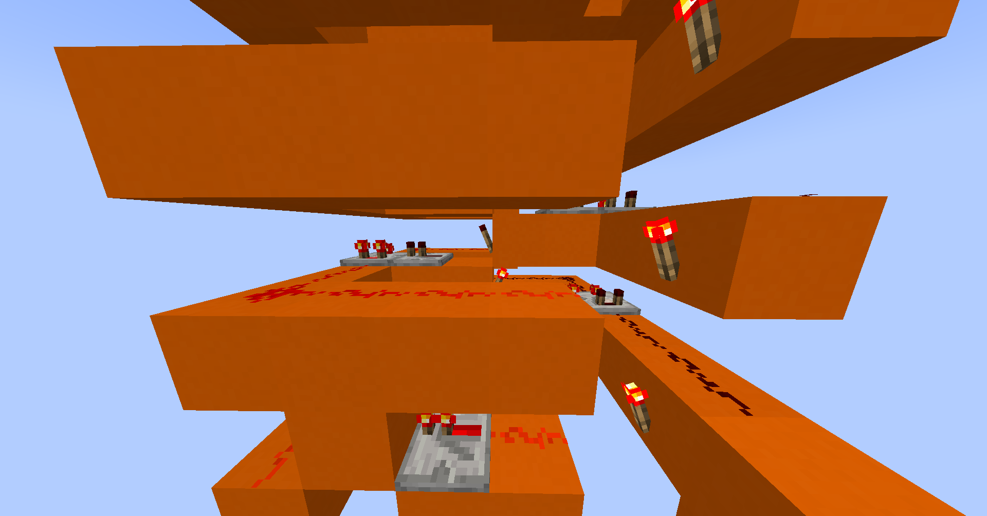
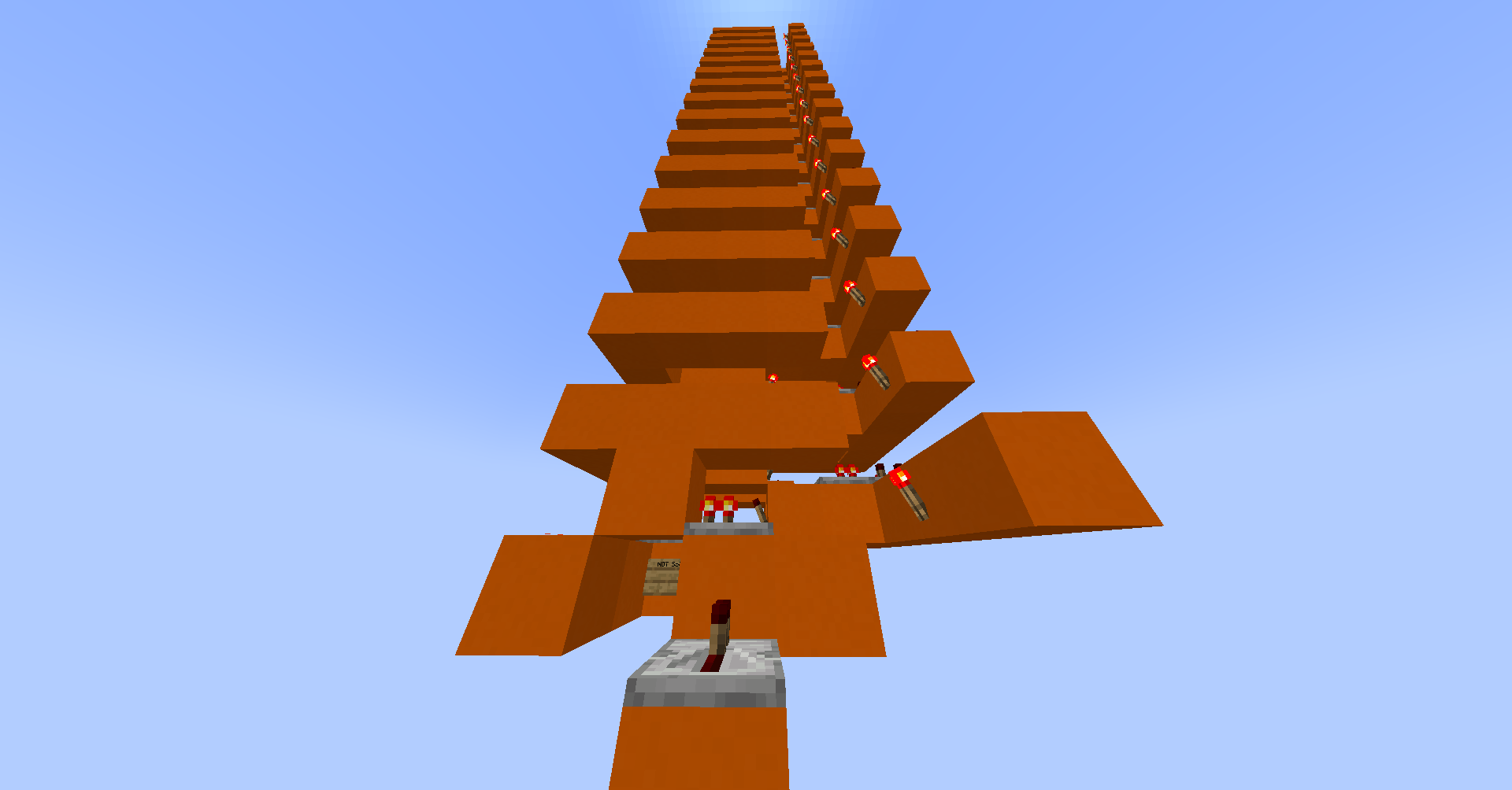
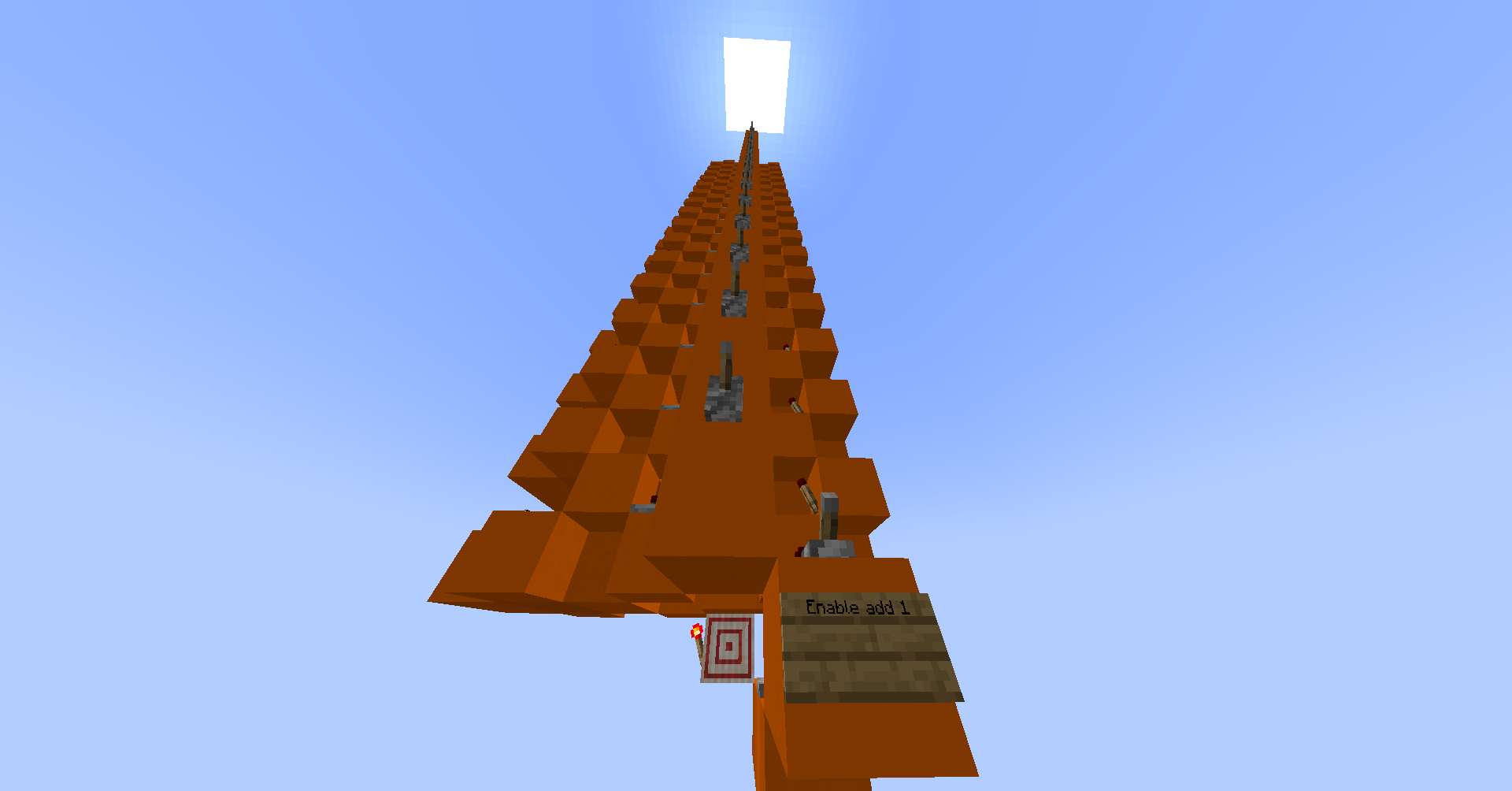
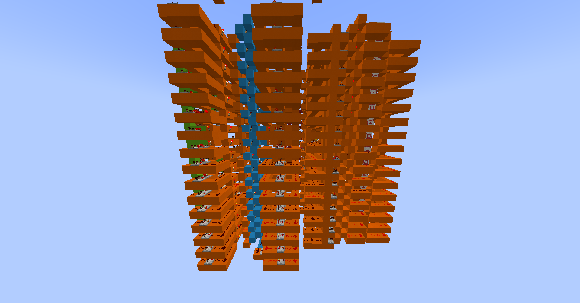
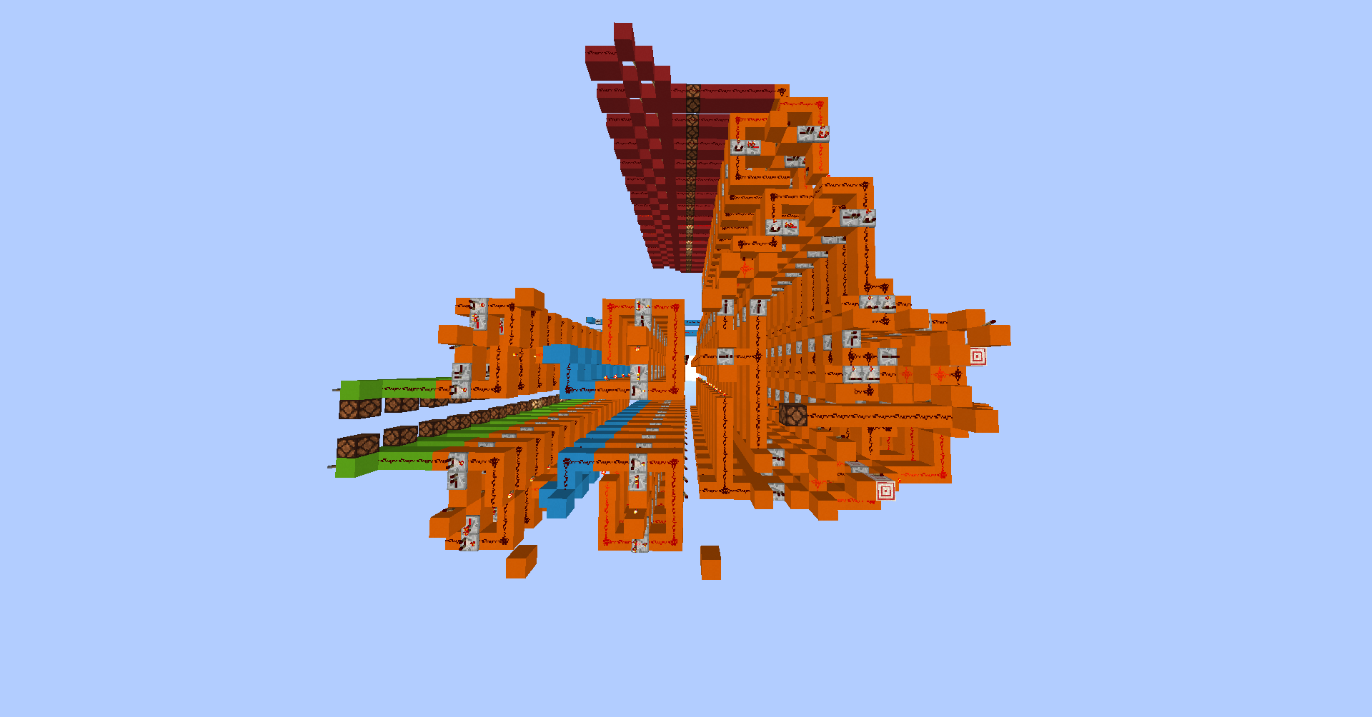
In a Harvard architecture, instructions are stored in read-only memory (ROM). The Hack computer is supposed to have 2^15 addresses in ROM, but this would be practically impossible in Minecraft.
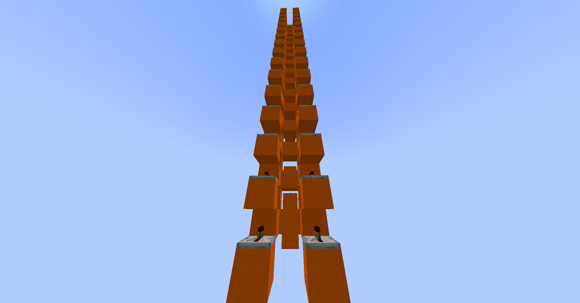
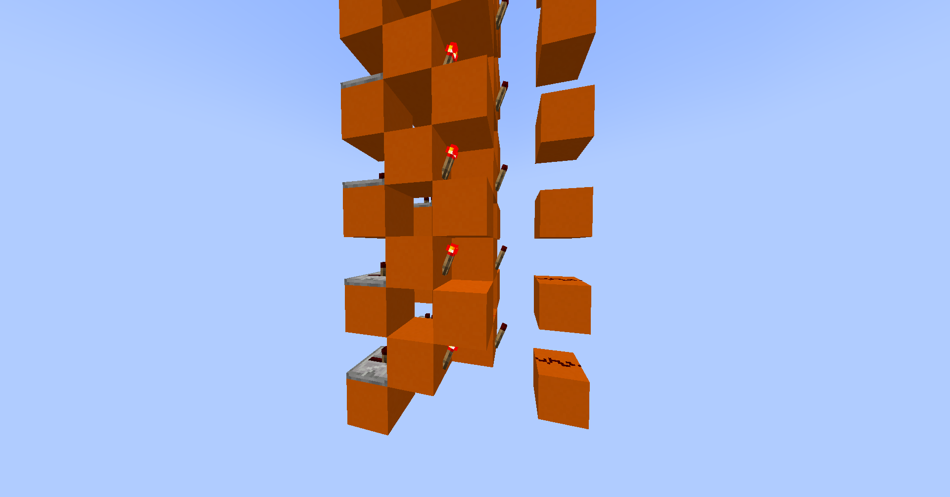
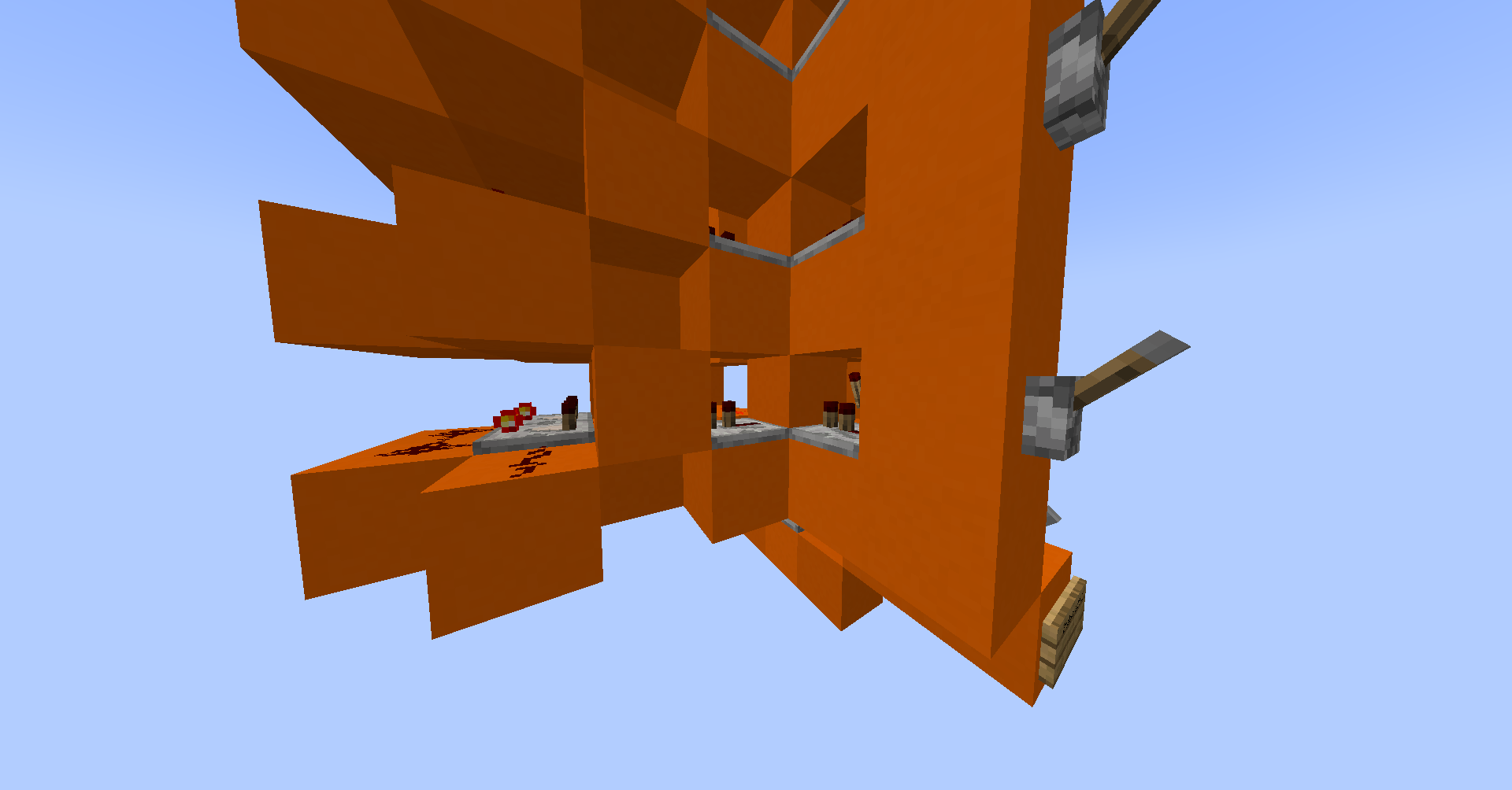
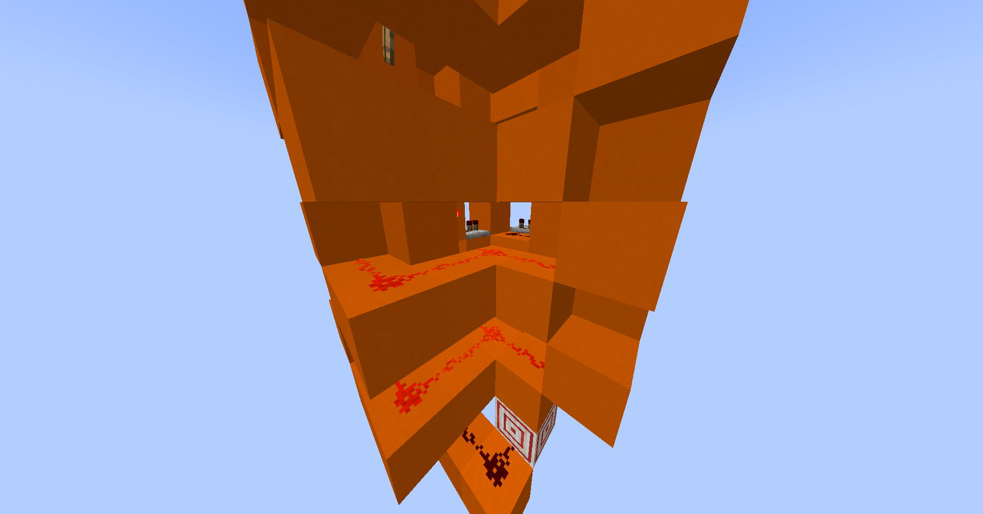
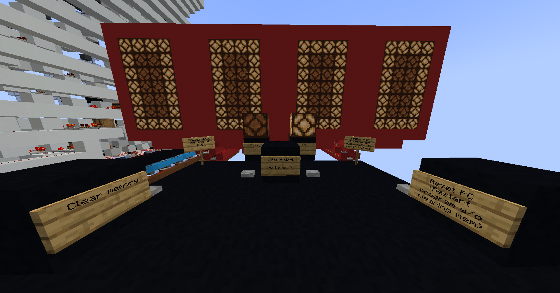
I wanted my computer to have a decently high address space without making the decoding logic too complex, so I settled on 64 instructions, meaning the addresses use only 6 bits, and any other bits are ignored. Instructions are stored using torches on the side of blocks, so that they power a bus when enabled. The presence of a torch means a 1 and its absence means 0.
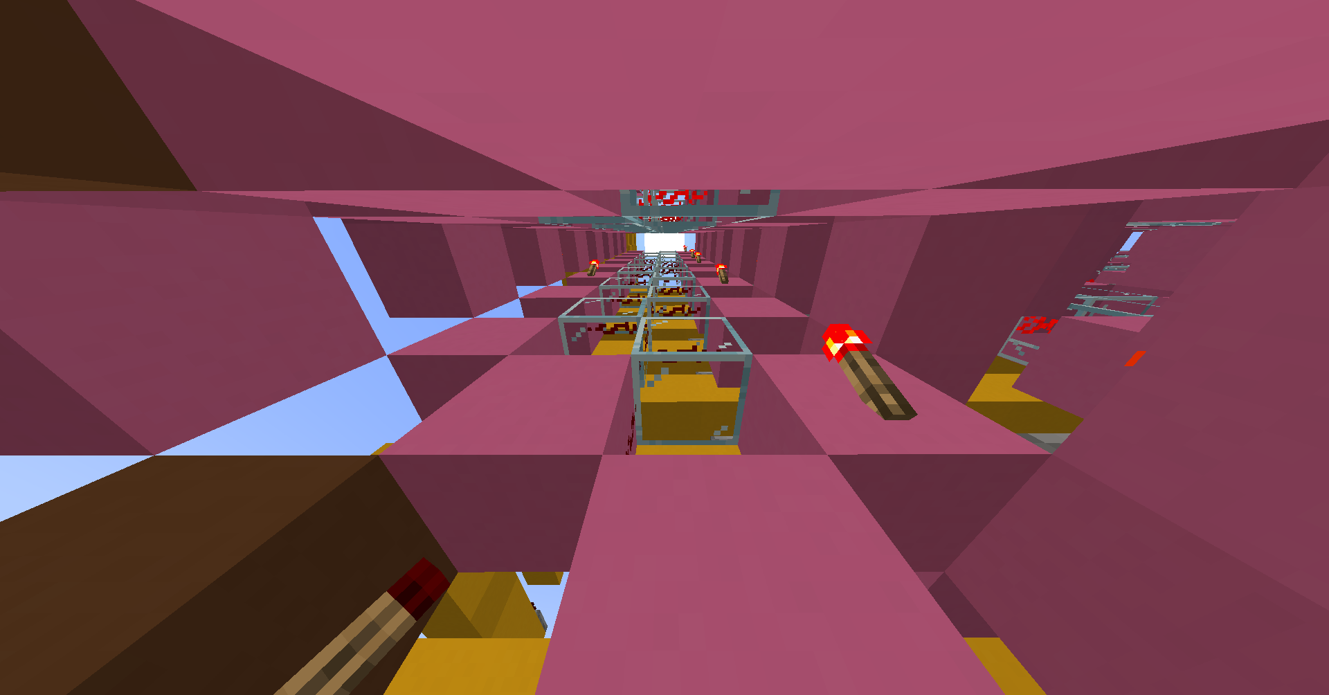
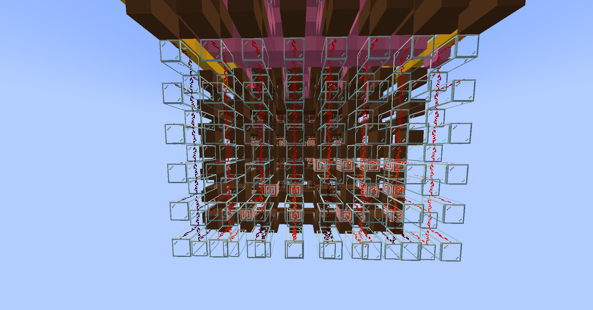
The example instruction in the images above is 0000010010110101, meaning store the value 1205 in the A register.
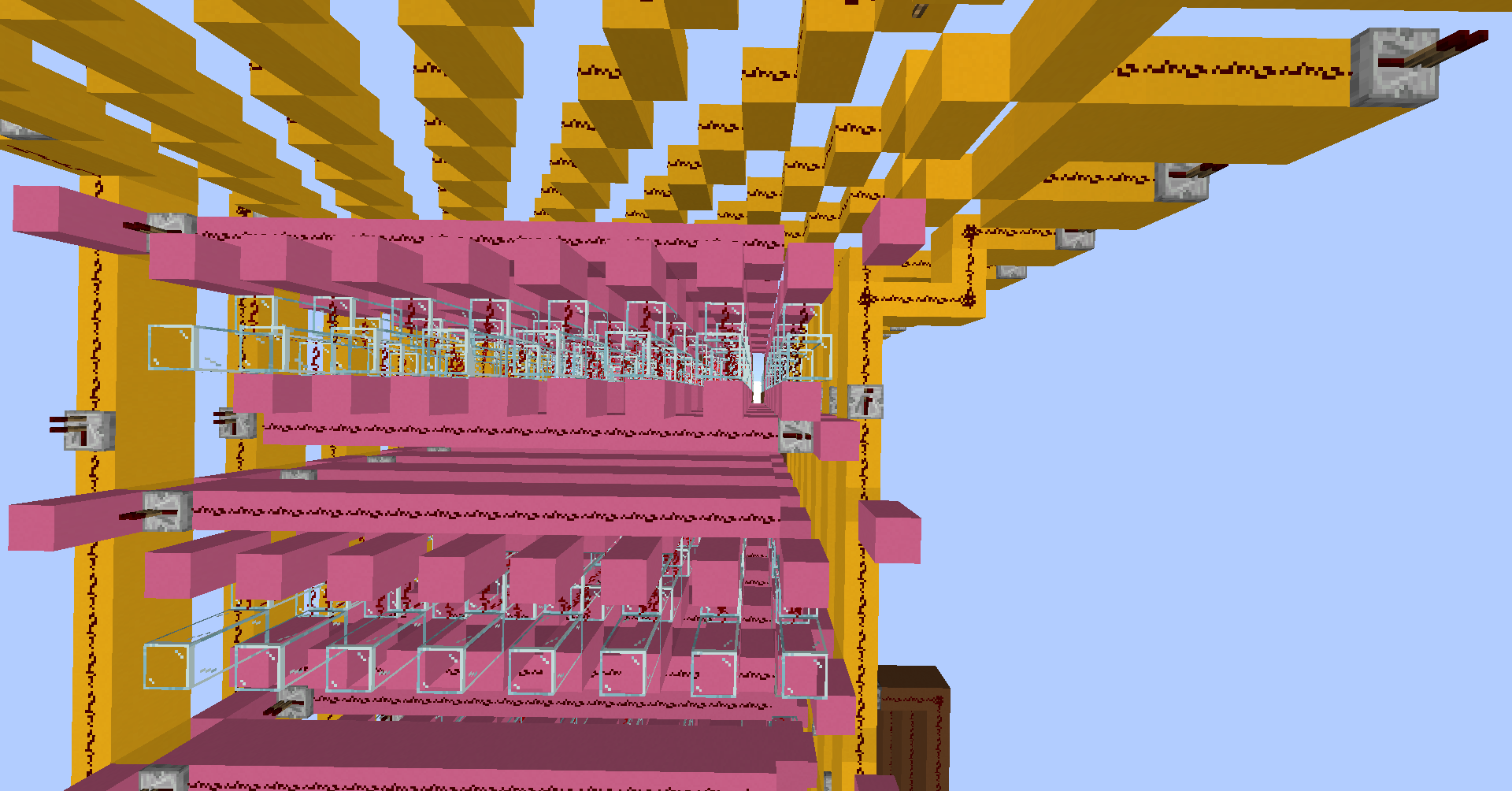
RAM
Random access memory is a bit more tricky than read only memory, since you also need an input bus and a write-enable signal. One potential way of doing this would be to use the registers from before in an array, and selecting between them for reading and writing. However, this approach is not very space efficient, and would not allow for many addresses. Instead, for the first time in this project, I used someone else’s design (credit goes to u/moothemoo_ on Reddit). The design I chose is able to store hex values, making it extremely compact. I also added some decoding logic to the bottom of the module to allow it to work with my CPU. I settled on 16 addresses, since even with this compact memory, it still takes up a lot of space.


Since the module stores hex values, I also needed to encode the binary value into 4 base-16 values, as well as decode the hex values back to binary. This memory design is possible because in Minecraft, redstone dust has a property called ‘signal strength’ which is a value between 0 and 15 inclusive. For reference, the white bus is data input, the grey bus is data output and the brown bus is address input.

Hex Display
I also wanted a way to receive output from the computer in the form of a display. A graphical display was beyond my capabilities (and probably beyond the computers as well), so I settled on a numerical display instead. My original plan was to create a five-digit seven-segment display, however this proved far too difficult for me to do efficiently (16 bits is a lot to convert to denary). As a compromise, I created a four-digit hexadecimal display, which would allow me to display a value from memory without any extra logic.
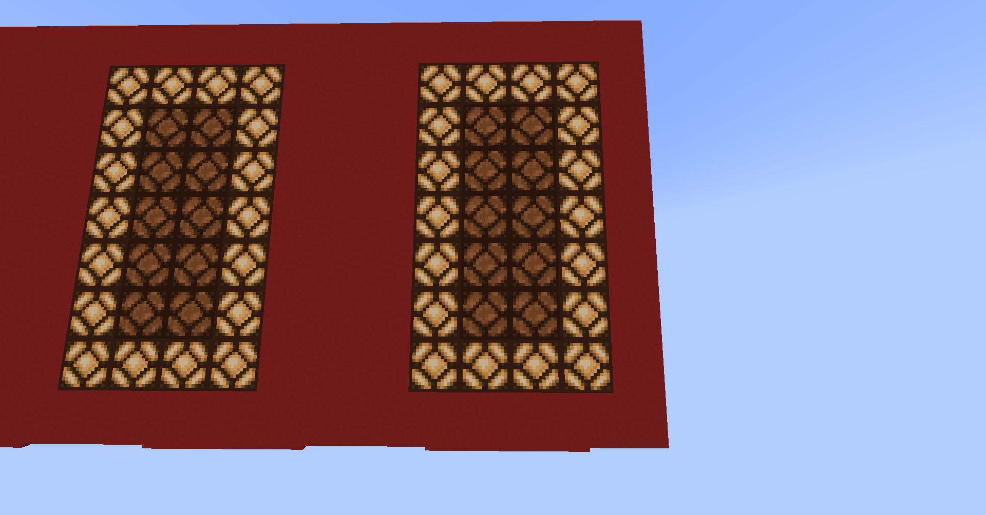
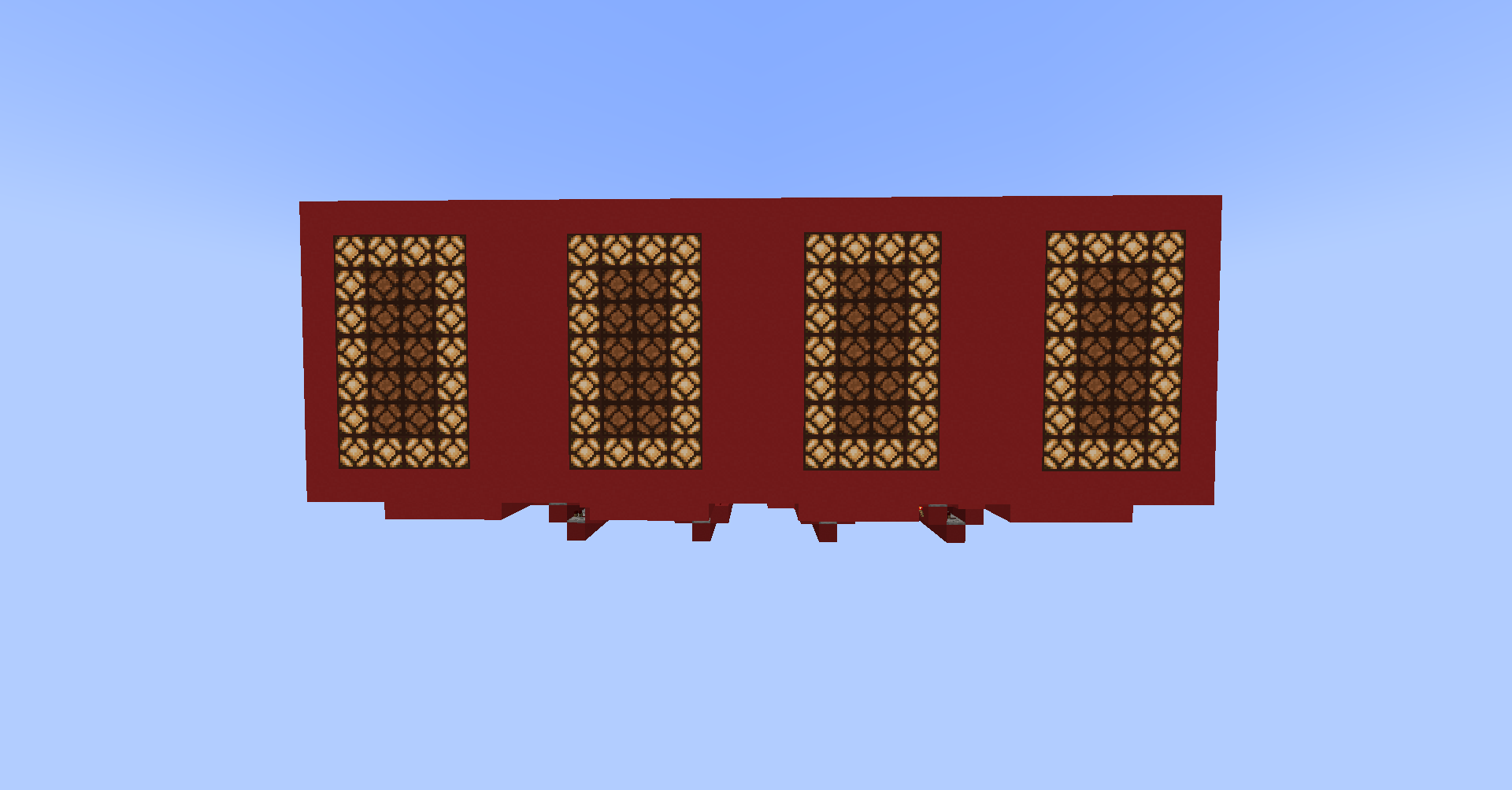
I connected the display to address 15, to avoid accidentally displaying working numbers instead of what the programmer actually wants to output.
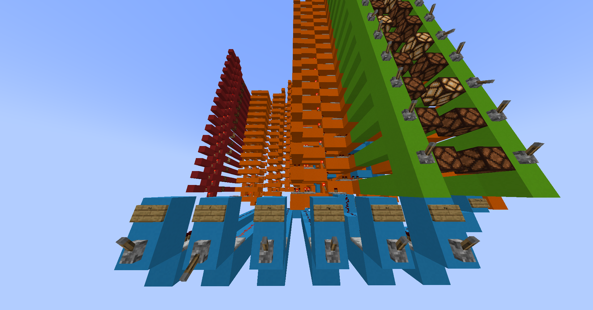
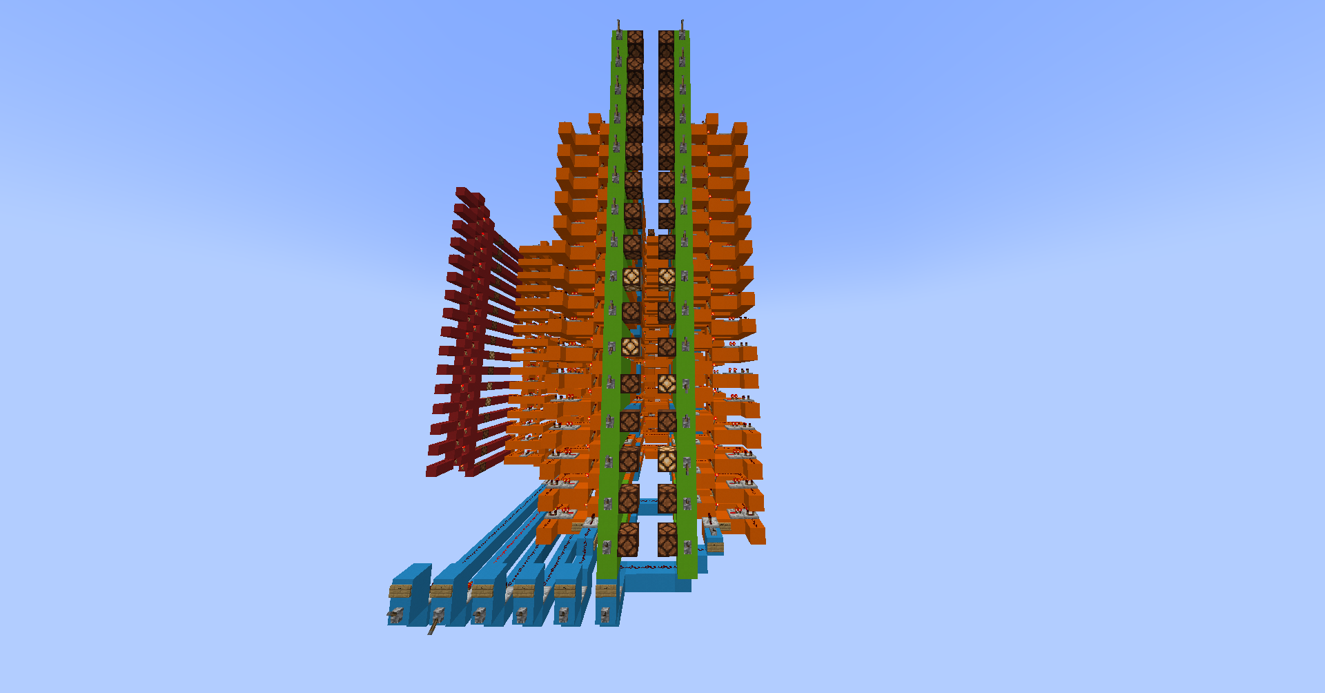
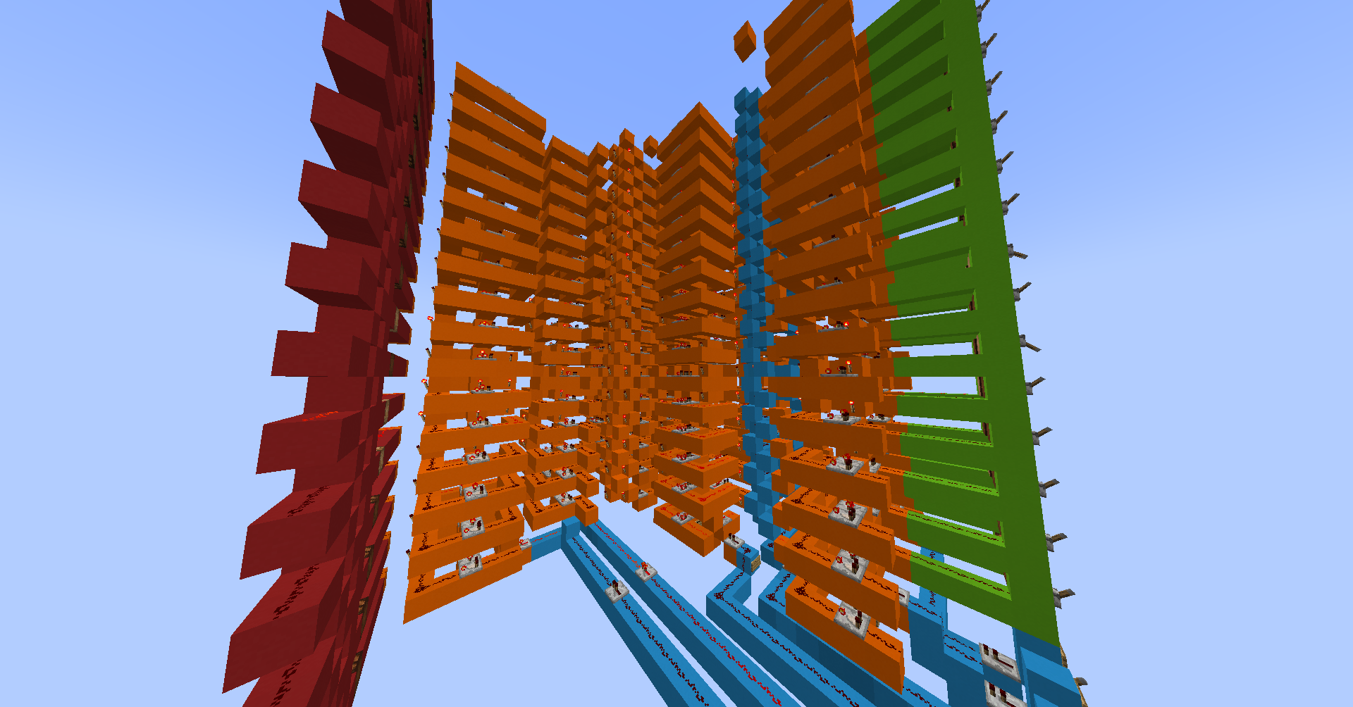
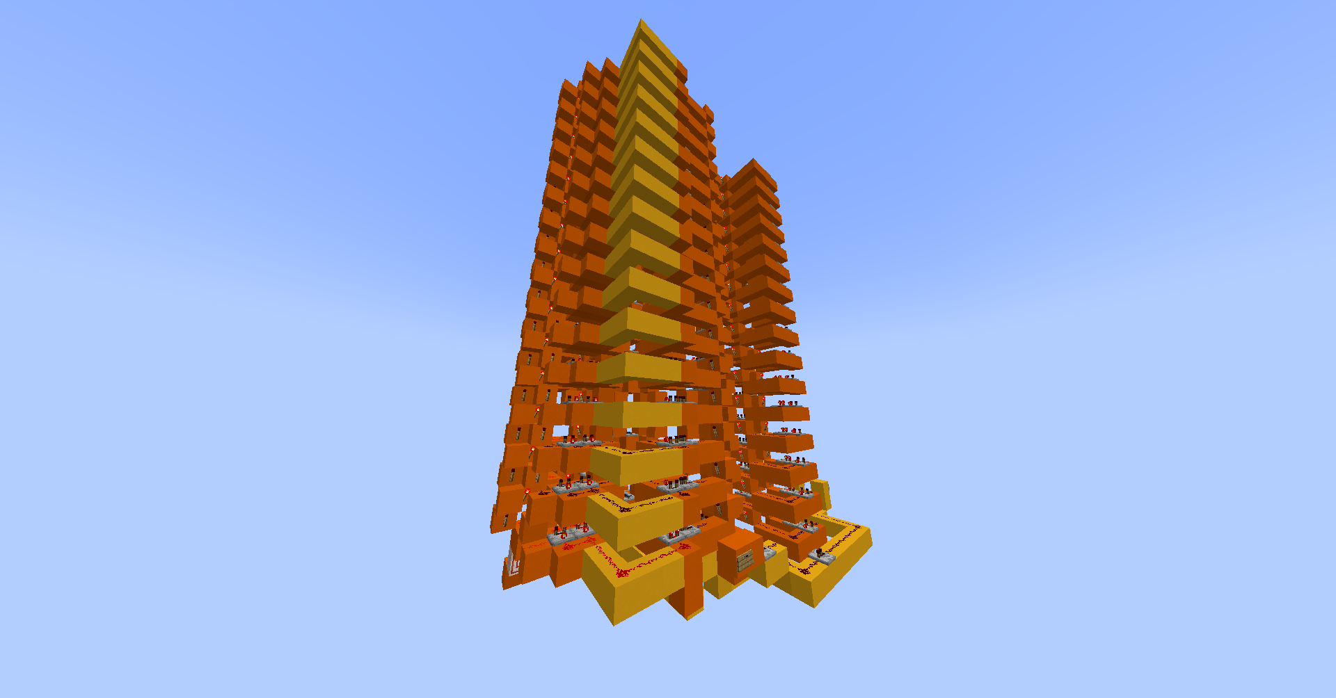
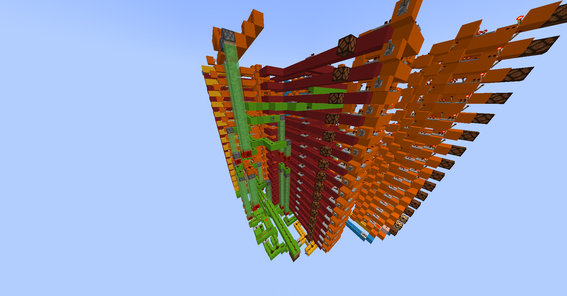
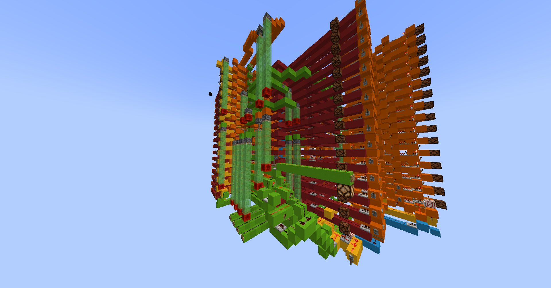
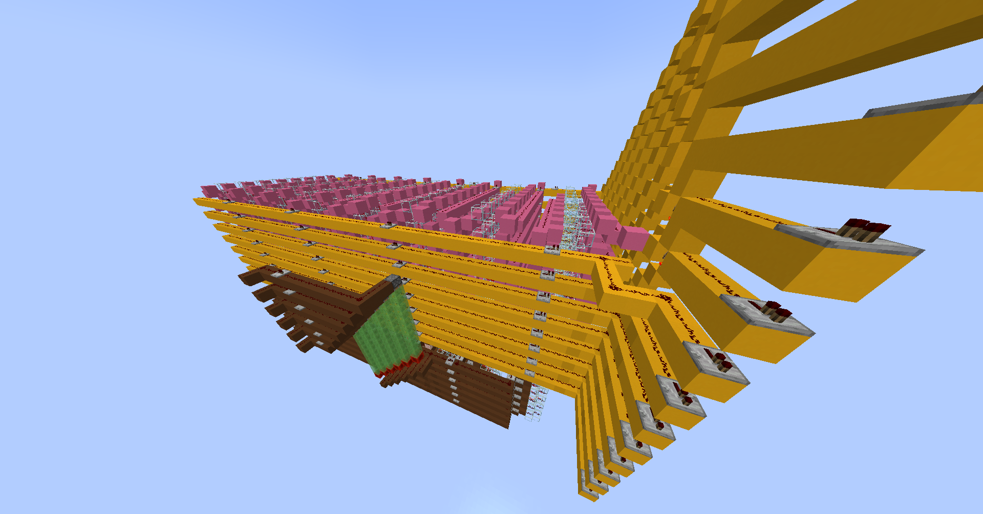
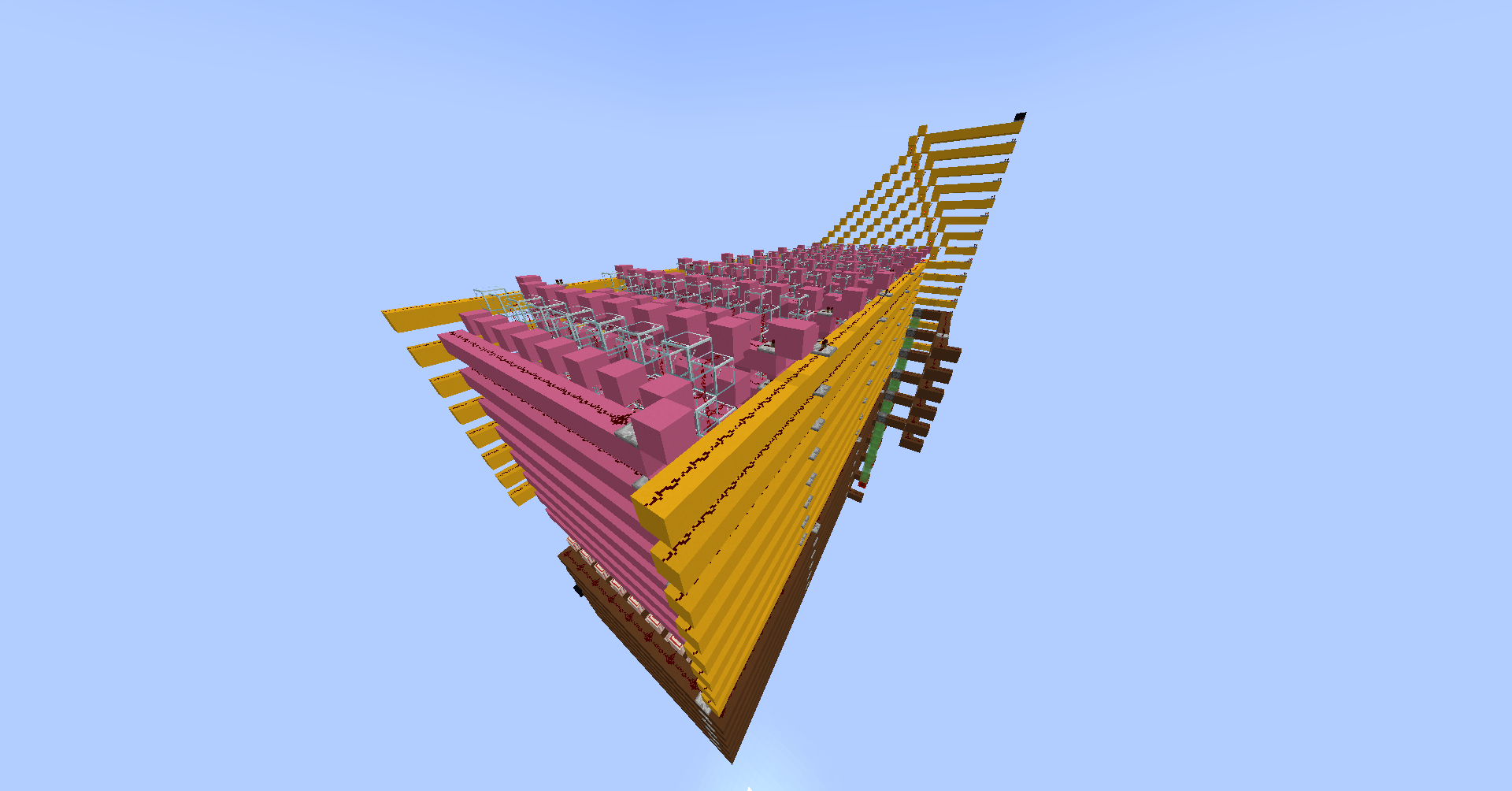
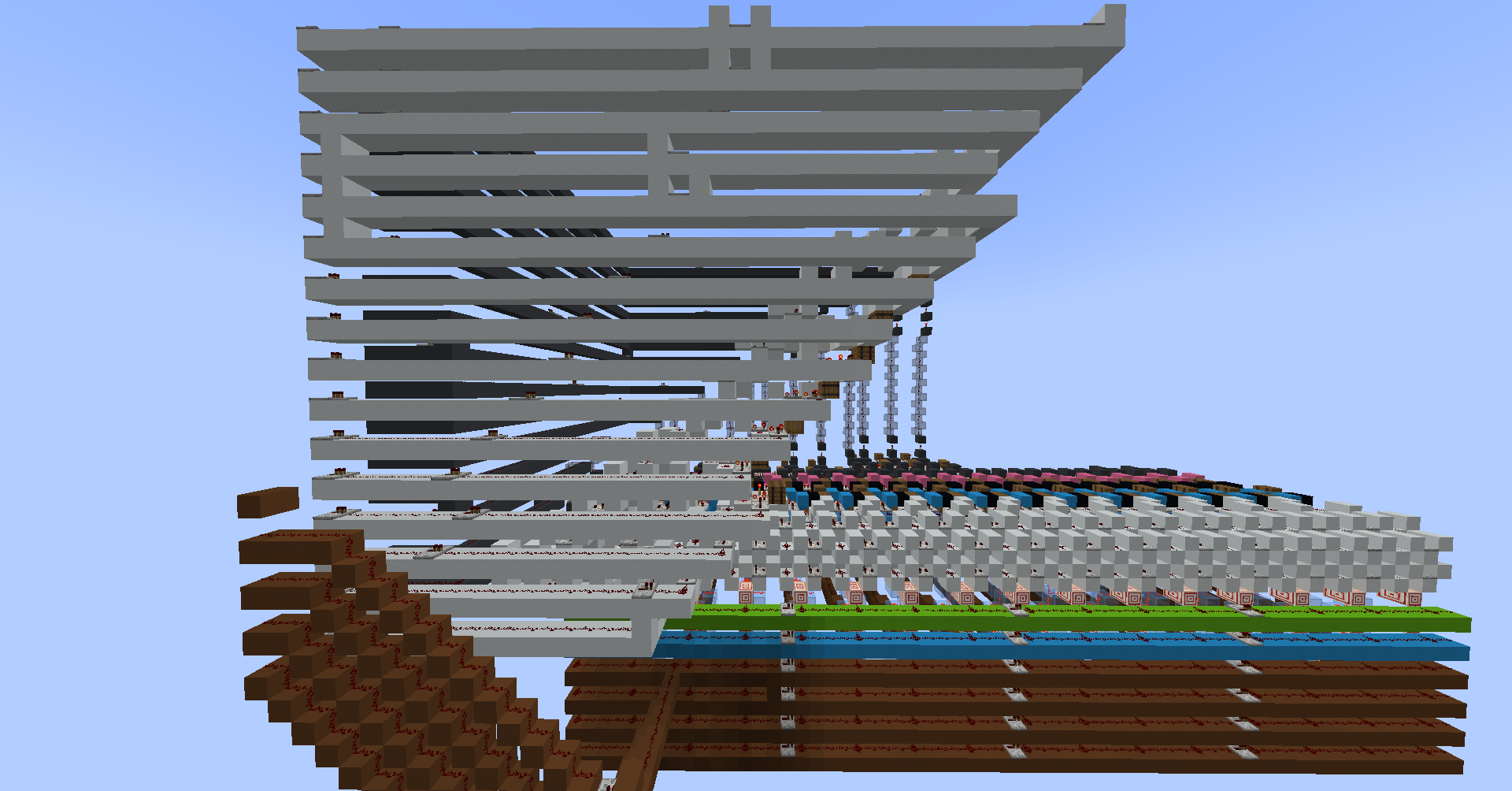
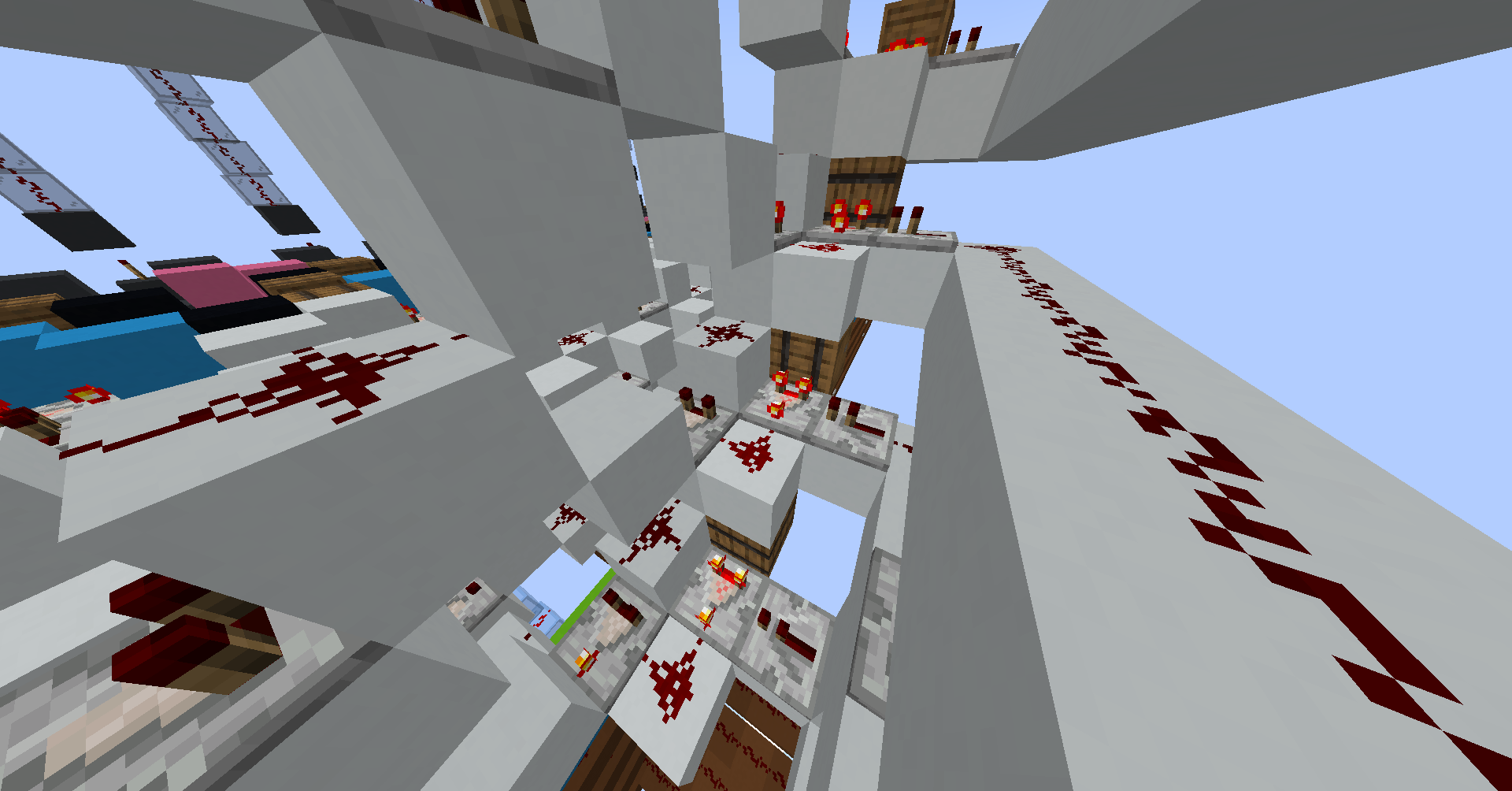
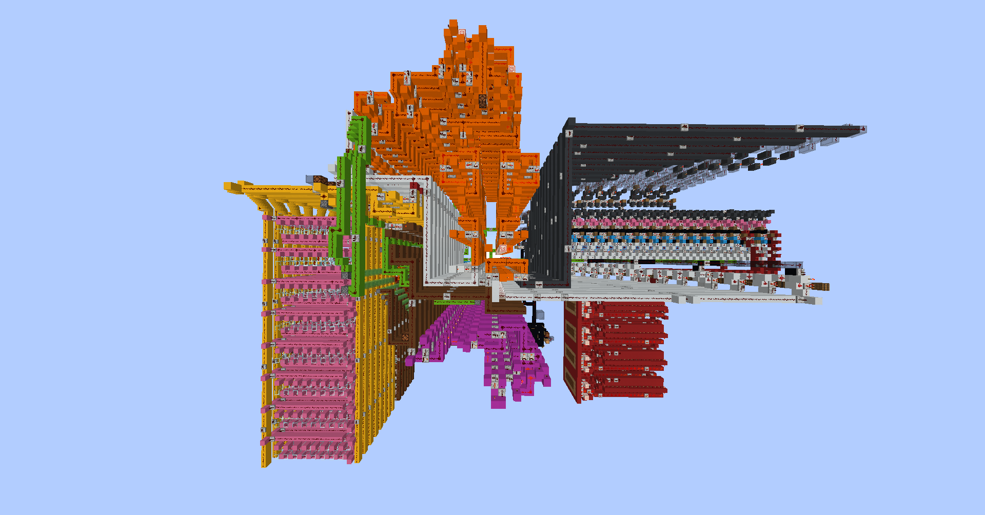
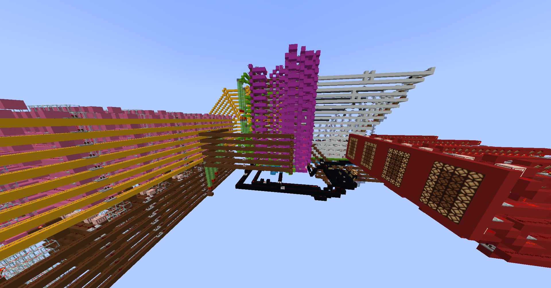
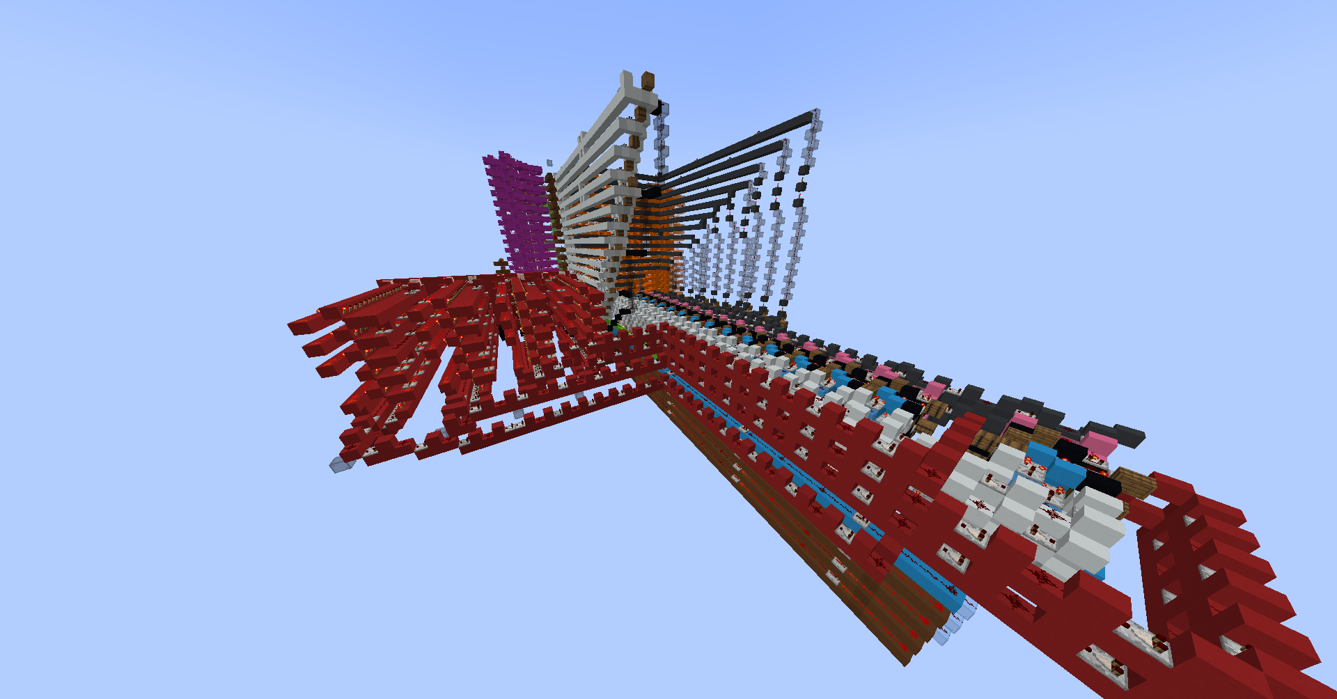
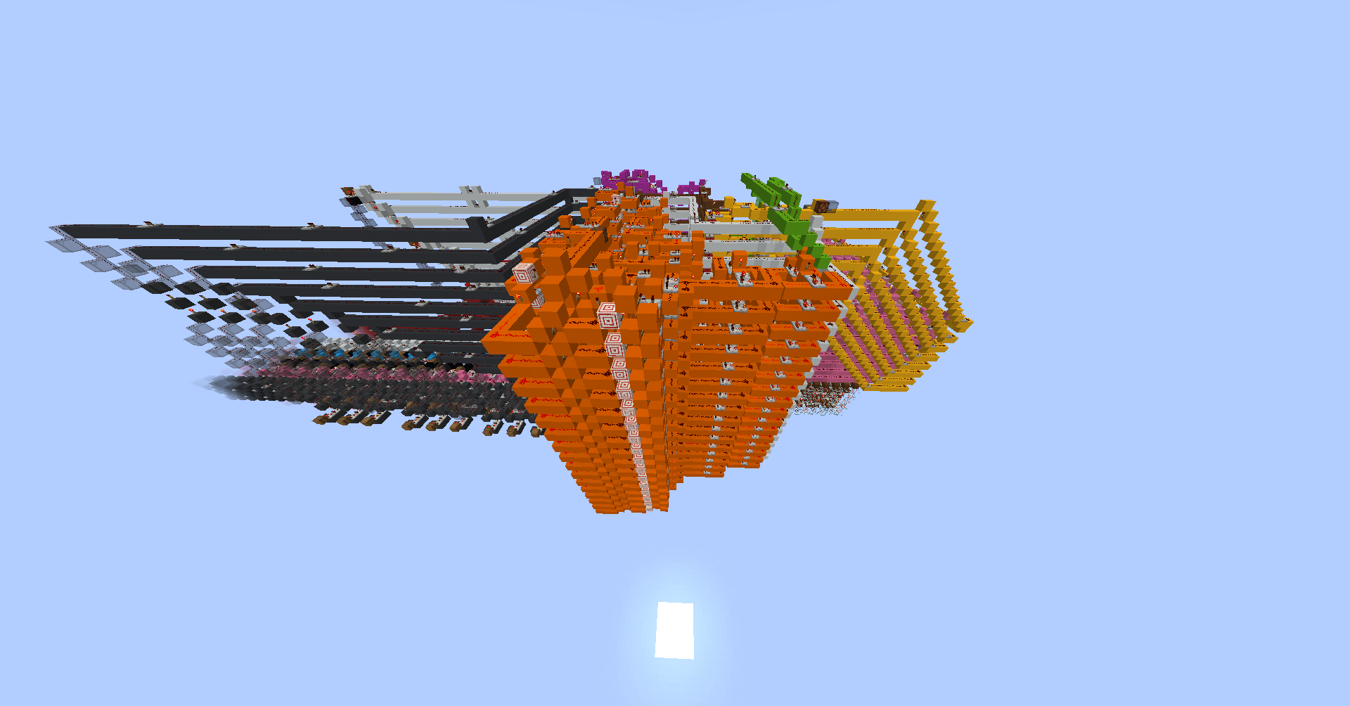
It’s all coming together
I could now put everything together: the CPU, ROM, RAM and display, as well as the clock and a control panel. I also did a little bit of cleaning up, like colour-coding everything to better see how everything is related. Once I’d connected everything, I tested a few programs that I’d written and copied (by hand) into swappable ROM modules. To my utter surprise, everything worked! Of course, I had done a large amount of bug squashing for each component, but I was still shocked that everything integrated without problem (and also that my programs were bug-free).
Conclusion
This project taught me a lot about the process of designing and subsequently building a computer from scratch, by forcing me to use a toolset that I’ve never used in this way before.
If you want to explore the computer for yourself, you can download the world here with the Fibonacci sequence programmed into it. Note that it was built in Minecraft 1.18.2 with Carpet Mod, WorldEdit and Redstone Tools.